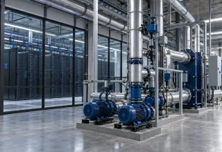
Talk about scaling AI infrastructure usually starts with megawatts: grid connections, substation queues, backup generators and power usage effectiveness (PUE). Water needs a place in that discussion too, particularly when a cooling system relies on evaporation.
Modern training and inference workloads concentrate a lot of heat in a relatively small space. Engineers designing new sites, or adapting existing ones, have two closely related questions to answer. How will they supply the power? And how will they remove the heat within the site’s water and energy limits?
For those teams, water can become a constraint early in the design. Here are the questions worth asking.
How much water does an AI data center actually use?
The 2024 report from Lawrence Berkeley National Laboratory estimated that U.S. data centers directly consumed about 17.4 billion U.S. gallons of water in 2023, equivalent to roughly 66 billion liters. That figure covers all U.S. data centers, not AI facilities alone. The report projected annual consumption of between 60 and 124 billion liters for hyperscale facilities alone by 2028. Those are modeled scenarios, rather than measured future demand.
There is also water consumed in generating the electricity a facility uses. An on-site total does not include that part of the footprint.
Rack density helps explain the pressure on cooling design, but it cannot tell you how much water a site will consume. Facility size, climate and heat rejection equipment matter too. Where a design relies on evaporation, operators need a supply plan for hot weather, when cooling demand and local water restrictions may coincide.
Why is cooling suddenly a water engineering problem?
Air cooling gets harder as heat loads become more concentrated. There is no universal 20 kW-per-rack threshold at which every installation must switch to liquid cooling. Equipment and airflow design affect that decision. High-density AI systems increasingly use direct-to-chip cooling; rear-door heat exchangers are another way to collect heat close to the rack.
Liquid cooling carries heat away in a circulating coolant instead of relying entirely on room air. The heat still has to leave the building, through equipment such as dry coolers, chillers or cooling towers. A sealed coolant loop does not necessarily involve evaporating water. Engineers have to consider flow, pressure, temperature and water quality across the separate equipment and facility loops.
Getting the suction-side numbers right starts with a clean NPSH calculation (see aspumps.com) for the actual installed geometry, not the datasheet assumption.
Where do pumps become the bottleneck?
Hydraulic performance helps keep servers available in a liquid-cooled hall. Leaks need attention, but less obvious problems can also cut cooling capacity and raise operating costs:
- Cavitation at the suction side. Vapor bubbles can form and collapse inside a pump when local pressure drops below the coolant’s vapor pressure. That can damage the impeller, reduce performance and increase noise or vibration. Available net positive suction head needs an appropriate margin above the pump’s requirement throughout its operating range.
- Oversized pumps. Excess capacity can leave a pump spending much of its life throttled or operating far from its best efficiency point. Selecting the pump and controls for the actual load helps reduce wasted energy and mechanical stress.
- Changing suction conditions. Tank level, coolant temperature, inlet restrictions and system pressure affect available suction head. Tower circuits also need make-up water to replace evaporation, drift and blowdown. Those circuits should not be confused with a separate sealed equipment loop.
Does recycled or non-potable water solve the problem?
Recycled or non-potable water can reduce demand on drinking-water supplies when used as cooling tower make-up. Suitability depends on the source and treatment. Dissolved minerals, suspended solids and biological activity may require changes to filtration, chemical control and material selection.
That does not make reclaimed water suitable for every part of the plant. A direct-to-chip loop still has to meet the equipment manufacturer’s coolant specification.
The financial trade-off varies by site. Lower supply costs may be offset by treatment, monitoring and maintenance. Water chemistry, discharge conditions and local prices belong in the comparison before anyone changes the supply.
What should operators be watching now?
Three practical checks give operators a place to start:
- Water usage effectiveness. Track annual site water use relative to IT equipment energy, usually expressed in liters per kilowatt-hour. Compare WUE alongside PUE and local water conditions. An annual ratio alone cannot describe seasonal supply risks or the water consumed in electricity generation.
- Suction conditions across the plant. Trend inlet pressure, coolant temperature, flow and relevant tank levels alongside vibration and maintenance findings. Investigate changes in the combined data rather than assuming one measurement will always reveal cavitation first.
- Supply and operating options. Assess the reliability of the water source, permitted discharge routes and the cooling system’s ability to operate during restrictions. Alternative supplies or dry heat rejection may help where technically and economically feasible.
Water planning belongs beside power planning. Following the cooling system all the way from the chip loop to its final heat rejection equipment gives designers a better chance of keeping a facility running through demanding weather and changing workloads. Those decisions need to happen while the site is still on the drawing board.
Last Updated: October 22, 2026